Drive Filter Designer
Link to Files (Main)
Link to Wiki
Link to Files (GUI)
This tool is to facilitate designing a drive coil filter for MPI. It is coded with Julia, an open-source language.
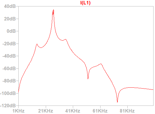
It works by taking in the coil parameters (L, C, R) and then picking values for the matching network and filter. The tool then designs the ideal inductors (to include the ESR), simulates the full circuit, and outputs the values and transfer function.
The main function is: DesignDriveFilter and the required inputs are:
-
LDrive, The drive coil inductance in Henries
- RDrive, The drive coil resistance in Ohms
- TargetZ, The target impedance you want to match to (I’ve only tested with real values)
- DriveFreq; The target drive frequency. Optionally this can be determined (assuming you have a value for CDrive that is reasonable) by setting “DetermineFreq” to be true
and keyword arguments (kwarg = default) are:
- CDrive = 1e6, The drive coil capacitance (Farads) it is very large by default to effectively bypass it.
- NumDriveElements = 1, This is an option if you have multiple repreated drive coil sections (e.g. 10 sub-coils that are wired in series, but you enter the value of a single section in LDrive, you can set this to 10).
- WireDiam = 2e-3, This is for the inductor designer. It makes sure the ESR of filter inductors are reasonable
- WireFillFac = 0.75, This is also for the inductor designer, it is a fill factor for the wires to account for using Litz. It simply scales the ESR
- PlotSrcR = TargetZ, This is not used. PlotFTs = true, Optionally plotting
- VSrc = 2, This scales the input for simulation DetermineFreq = false, If you want the solver to determine the most appropriate drive frequency set this to true. Must include a CDrive then
- AddNotchFreq = nothing, If you want a notch frequency e.g. 2f0, or 3f0, set this to the frequency you want to notch in Hz
- FilterZ = TargetZ, The characteristic impednace of the filter
- RDampVal = FilterZ, The value for the damping resistor.
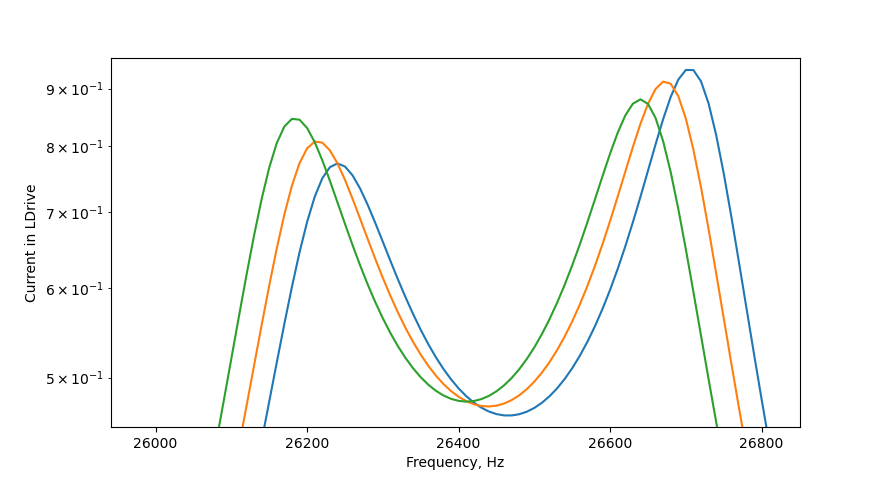
- PerturbTxReactance = nothing, A generally UNUSED INPUT. It can be used in the case if you want to perturb the matching section you can set this to some value (Ohms). This allows for fine-tuning the frequency response and therefore optimize the filter for stability.
Also included are other useful functions such as the toroid optimizer, which creates a toroid core shape that has minimal ESR (See “D-Shaped toroidal cage inductors” P.N. Murgatroyd & D. Belahrache,1989)